A1200 Re-cap
I know this has been done hundreds of times before but here’s a run down on my own re-cap experience. I had not attempted to re-cap any Amiga before this so it was a first for me. I had thought about getting someone knowledgeable to do this for me but as by now I’d had quite a bit of soldering experience thought I’d give it a go.
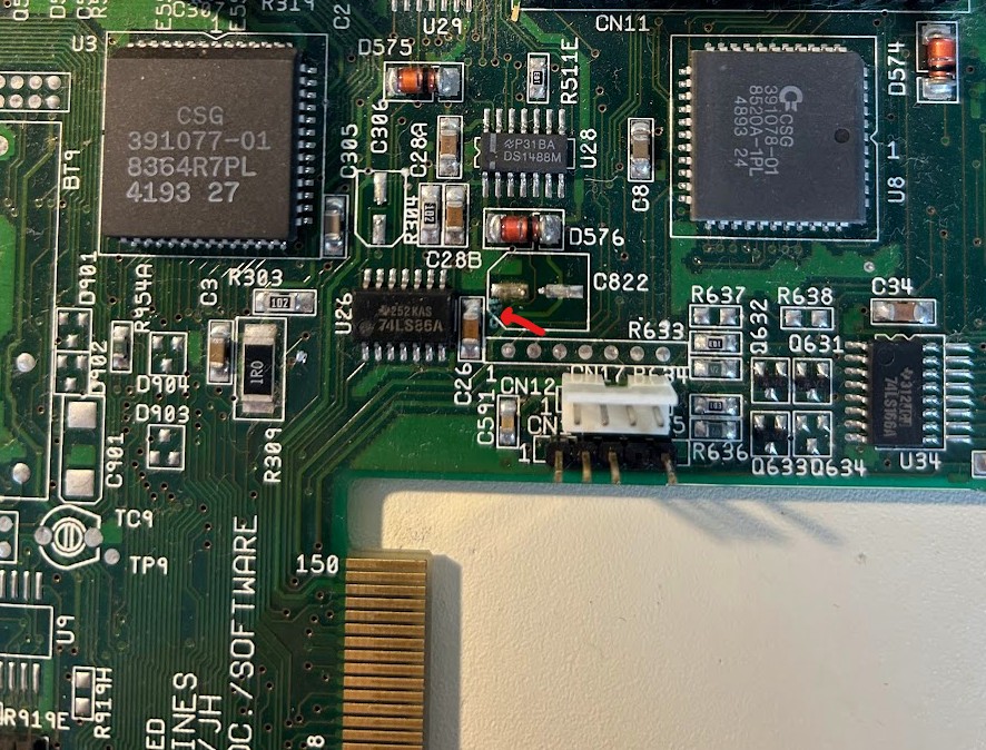
I have two A1200s. One I bought from Amigakit.com (just as the main board), recapped already with timing fixes. But I had another which I’d owned since the mid 2000s. While I had kept a close eye on its caps over the years there was never any sign of leakage (or smell) and all the caps solder joints were shiny. I was pretty certain that it had the original caps on it though. It ran fine so my thinking was if it’s not broken don’t try and fix it. But on a recent inspection I noticed something very small, the tell-tale signs of a corroded trace just near C822. It was time for a recap!
With new Panasonic electrolytic caps already ordered a year ago I didn’t need to wait for parts so got straight into it. The main decision at this point is around the technique to use when replacing the caps. This can turn into a bit of a religious argument for some people and there’s more than one right way to do this. The method I decided to go with was the ‘Chris Edwards Loraina cutting’ method. For those of you who don’t follow Chris Edwards YouTube clips, his method involves cutting the old caps off with a sharp pair of cutters. You snip off the metal cans, snip off the metal ‘nipples’ on each leg and then remove the plastic disc at the base until you’re left with a couple of soldered legs on each pad. From there it’s a simple matter of using the soldering iron to remove the legs and cleaning up with braid and alcohol. Chris does a great video on this so no need to try and picture what I’m describing here.
C822 was my first target and with a bit of trepidation I took the plunge and cut off my first capacitor. Well that was easy! With the cap off it was clear it had started to leak. Onto the next ones. All went smoothly and now I was left with just one, C334 which sits hard up against the keyboard connector and an RCA and floppy port on the other side. Some like to de-solder the keyboard connector to get better access but for me that was going to be risky as I didn’t have a proper solder sucking de-solder station. In addition this also seemed the riskier option just because the more soldering/de-soldering the greater the risk to lift a pad. The snip method gets a little hard here as you can’t get the cutters in there at a good angle. But you carefully remove the sliding plastic piece of the keyboard connector to give yourself a bit of extra room. Holding my breath, I cut the top off on an angle that I wasn’t happy with, but it did the trick. With the top of the can off it was easy to snip down and very gently remove the rest of the can.
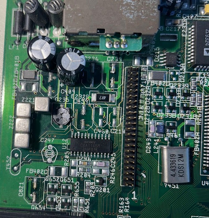
All up I discovered a few other caps that had started to leak that was only noticeable once removed. Alcohol and cotton buds later and it was all cleaned up and looking great. Since I was on a roll I decided to also remove my RF modulator. I wasn’t going to use it and I had plans for using that location to get my scan doubler/flicker fixer port mounted. With beefier ground planes I switched to a larger solder tip and cranked up the temperature. Manual solder sucker and braid cleared the holes and some gentle prying while the solder was melted eased it out.
I decided to do the through holes next even though I thought they were likely fine. I ‘walked’ them out by using the Chris Edwards method. Meaty ground plane meant I needed my fat solder tip and some extra heat. I tested them once out and found all within spec which is what I expected. I didn’t really need to replace them.
I was ready for the re-cap and with the RF modulator out decided I didn’t need to put C236 or C239 back in. My method involved putting a small amount of flux and then solder on one pad first, then using tweezers position and hold the new capacitor and heat until it’s sitting right. Now you can do the other pad without needing to hold it or worry it will move on you. C344 just by the keyboard was easy to solder in. The new cap is smaller than the old and with a fine tip and steady hands you shouldn’t melt the keyboard connector.
Through holes were trickier just because I had problems clearing the ground plane hole. I cut the legs down on the new cap so they weren’t so long and so that the positive was longer than the negative. I had easily cleared the positive hole so you slid the leg in there until the negative leg is up against the solder blob in the hole I couldn’t clear and then with the board on its side it’s a somewhat easy job to heat the underside while holding the cap until the negative leg slides through.
Final double check to make sure the caps are all in the right way (don’t want to swap polarity) and it was ready to boot up. Everything worked great and examining my work I was very happy with the outcome which looked very professional if I may say so!