A501 Rev8 RAM Expansion Build
This was my first time building something from scratch for the A500. I decided on the A501 RAM expansion board because it was cheap to get made at PCBWay, was going to be easy for me to solder and allowed me to re-create an old Amiga component which is just about always damaged by battery electrolyte. While there are no end of A500 RAM expansion boards I really wanted the original Commodore factory look.
The project on PCBWay is here. It includes a basic BOM (in German) but otherwise no other instruction. After building my first card and finding it didn't work I then realised there was a difference between the 6C and 8 version of this card and depending on what situation you're building it for (A500 or A500 plus) you need to make some adjustments to jumpers.
The clock section of the board is optional. You could leave it off completely if you wanted to. If you look at PCB explorer you'll be able to see which components relate to the clock only. I left the de-coupling electrolytic capacitors in place.
The OKI clock chip and the trimmer pot beside it is also hard to find. I ended up ordering both these from AliExpress, along with spare RAM chips.
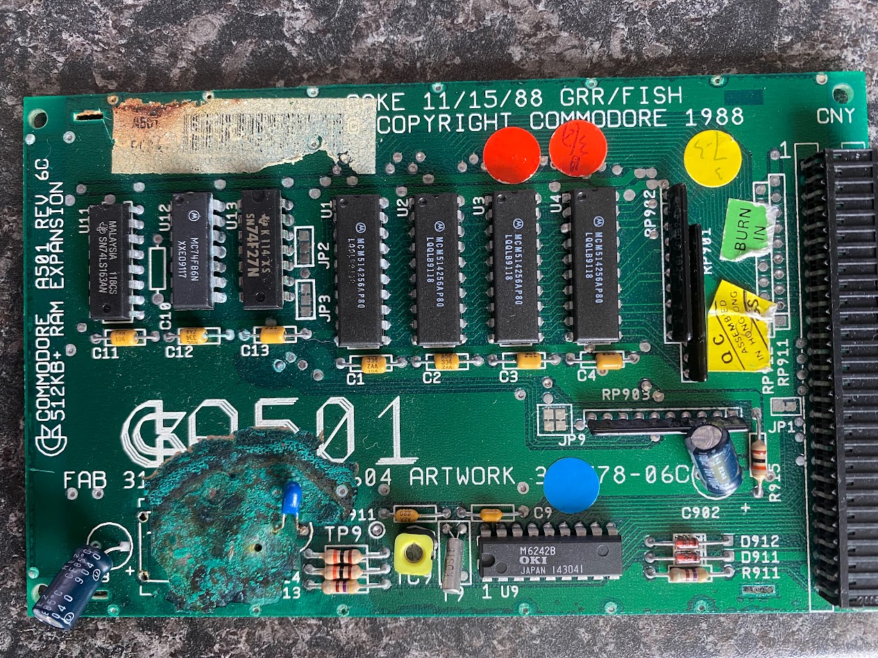
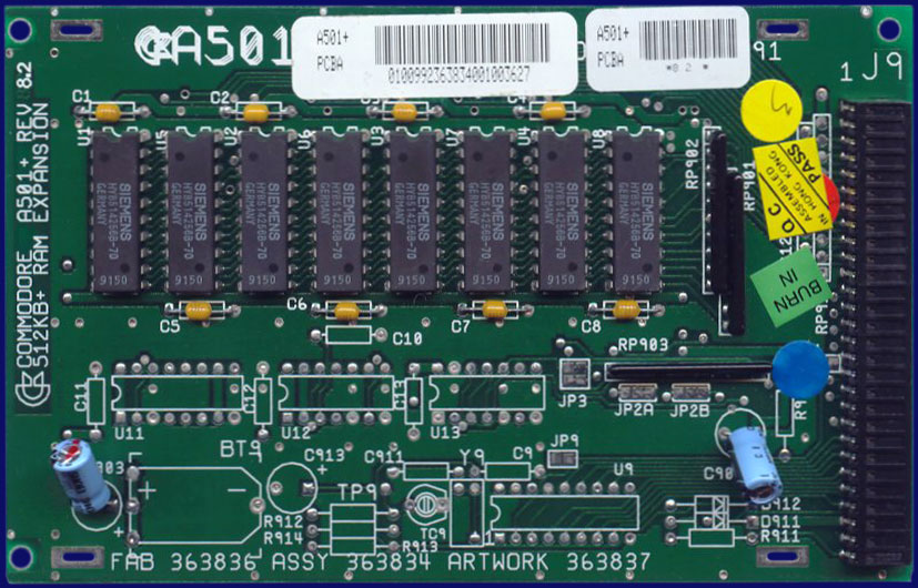
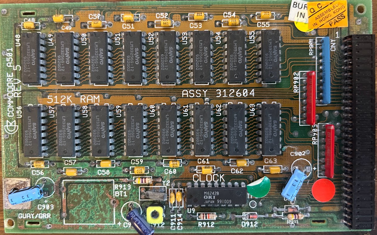
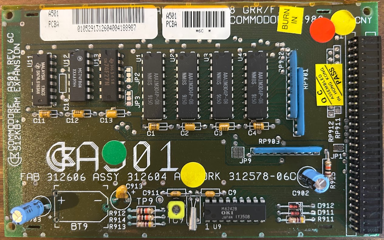
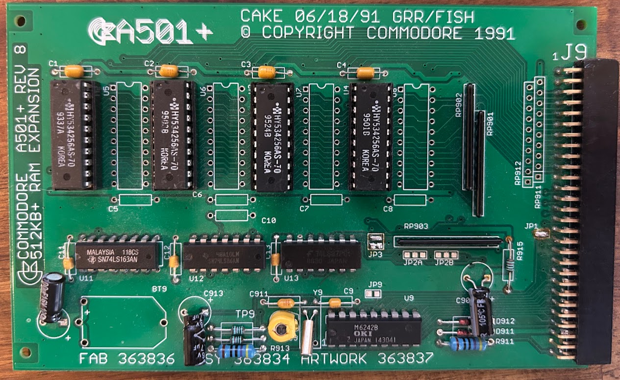
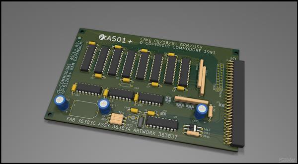
The Rev8 of this board available on PCB Way is not quite the same as the Rev6C which we're probably most familiar with. It's a later design which allows for the population of either 512K or 1Mb of RAM.
Reviewing the PCB design and the original 501 Rev6C and Rev8 schematics I need to do a few things for this to work on the A500, populated with 512kB of RAM
- Despite looking very similar the rev 8 is not the same as rev 6C the JP9 pins (JP3 on rev8) are rotated 90 deg
- DRAM goes into U1 to U4 and the rest are left empty if only populating with 512kB
- PCB connector on the new PCB uses the newer type. The original Amiga one had wider pins that connect to the PCB and apparently hard to get now. I got 2 x row of 40 from AliExpress which I then cut down to fit
- The parallel resister network 68 ohm seem to be hard to find, check out Mouser. But you could just install small 68 ohm resistors (see my picture of of ZIF socket ram tester below). Have to use ‘parallel/isolated’ type not the ‘exclusion’ as on AliExpress as those type have a bussed common pin for all resistors
- Memory can be put in DIP sockets but you'd want to check to make sure there's adequate clearance for the keyboard. RAM chips are at the bottom edge so tightest area
You need to review the “Amiga 500 plus” service manual to ensure you set the jumpers correctly. This service manual has the rev 8 card which you're building here. The jumpers on the 6C and 8 are different although mostly the same, just labelled differently.
A501 has RAM ‘refresh feature’ which according to this forum topic is needed for Agnus 8370/71 versions only. This is not used on the 500+ version of this card: What almost all of these expansions (including this one) failed to acknowledge was that the existing 8370/71 Agnus couldn't properly refresh 256Kx4 chips without helper circuitry, so this expansion should better only be used on an A500 with at least the 8372A Agnus. With the 8370/71 it's prone to frequent Guru's unless you populate U11-U13.
https://forum.amiga.org/index.php?topic=72604.0
JP3: On the Rev 8 boards when looking at it the right way up (text is right way up to read) pin 2 2 are top and 1 1 are bottom (ie 1 1 pads are directly above JP3 silk screen. This is as per Amiga PCB Explorer.
2 2
1 1
This PCB can be used in both A500 Rev5/6 and Rev 8. When sold as a ‘plus’ it comes with RAM only, no RTC components and no U12/13 logic chips.
You need to check the A500 PCB but in general 8370/71 = Rev 5 (although some early Rev 6?) and most Rev 6 have the 8372B.
3 ways to build the board:
- If going into A500+ all RAM chips and their Caps required along with resistor array 01, 02 and 03. C902 and C903 are also populated. No need to alter any jumpers.
- 2 x 100uF 16V electrolytic
- 3 x 68 Ohm 10 ping isolated/parallel resistor arrays
- 8 x axial 0.33uF
- 8 x 20 pin DIP sockets
- 8 x RAM chips
- If going into A500 Rev6 with Agnus 8372 only populate U1-4 RAM chips and their caps, same 3 resistor arrays, same capacitors plus the clock circuit components but ignore U11-13 and their caps. J1 needs bridging if this is to be detected as ‘slow’ memory. JP2A and 2B leave as is, (unless going into a rev5 or earlier, U11-13 required). JP3 need to sever traces and then bridge 1-2, 1-2 (so looks the same as rev 6C JP9)
- 2 x 100uF 16V electrolytic
- 3 x 68 Ohm 10 ping isolated/parallel resistor arrays
- 4 x axial 0.33uF
- 4 x DIP sockets
- Optionally clock circuit
- If going for max compatibility populate it as #2 but add A11-13 and their caps. JP2A and 2B need to be set in addition to J1? I never got around to testing this.
To test the memory range for 512kB it will be $00c00000 - $00c7ffff
I never bothered to fit the battery holder or a battery. If you do decide to fit a CR2032 make sure to disable the charging circuit by replacing the 470R resistor at location R913 with a diode (1N4148). I also thought about ordering one of the original Varta barrel batteries. Why? Because it would make it look factory! The reason I decided to build a new A501 was because of battery damage but when you think about it, building one in 2025, how many years until it leaks?
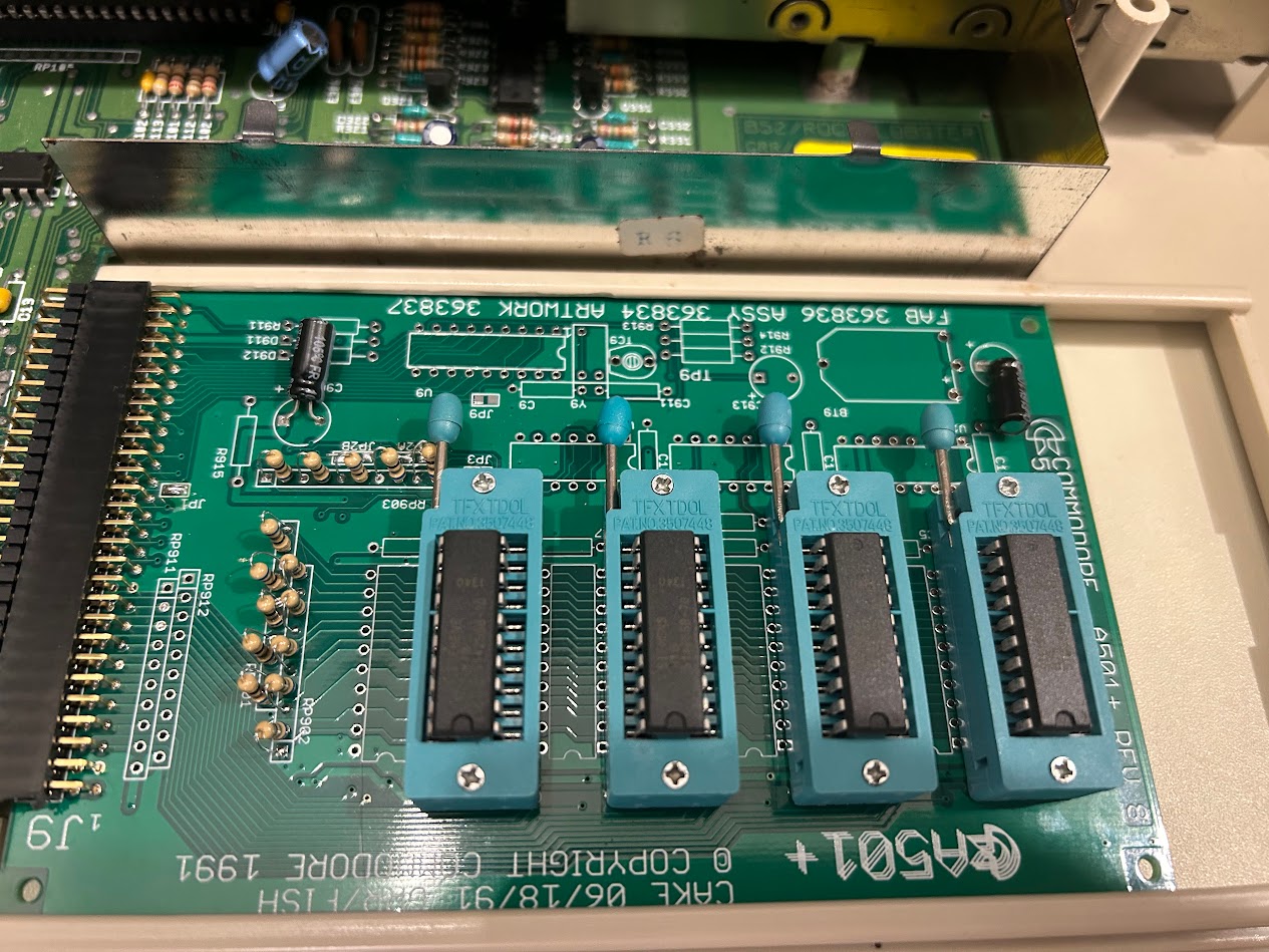
RAM Tester
With excess boards I also decided to build another one, but this time one which uses ZIF sockets for the RAM chips. I wanted something which I could use to easily test RAM chips. The A501 Rev6C and later used the same RAM chips as the Rev6A & Rev8 A500 main boards. It's also the same RAM chips used in the A590 Hard Drive expansion. You install your RAM chips, plug into your A500 and boot into Amiga Testkit and perform the RAM test.