Amiga 1200 USB Right Mouse Button
A not uncommon issue for an A1200 using a USB mouse adapter (DB9 to USB) is for a the right mouse button to not work. I encountered this on my Rev2B motherboard. There was a couple of good discussions on this issue and it is quite well explained. There were a number of ways to fix it but I decided on what I saw as the easiest, replacing a couple of 68R resistors with ferrite beads. But when it came to the fix there were a few questions left unanswered.
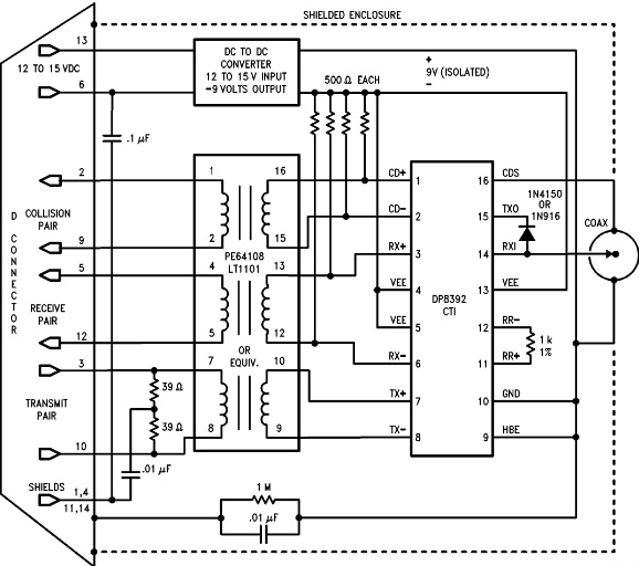
The link here provides someone's investigation into the issue. The fix is to replace 2 or 4 resistors with inductors 'like they use on the A4000'.
The missing information in the above websites was what components needed to be ordered? It only talked about ordering the same ferrite beads as used on the A4000. PCB explorer for the A4000 didn't answer this question so I went looking at the Re-Amiga A4000 BOM for the answer.
So here's what you need:
- You'll need 4 x 1206 sized 600R SMD ferrite beads. The ones I ordered were BLM31AJ601SH1L and you're best to order a few extra in case you loose one or two when attempting to remove it from its packaging or soldering it to the board
- I only did the one DB9 port, the one right at the end. That's the one I plug my mouse into. If you are not using your mouse in the other DB9 port don't worry about replacing those resistors (if it isn't broke don't fix it)
- Tweezers, flux, fine tipped iron, magnifying glasses, good light and extra solder
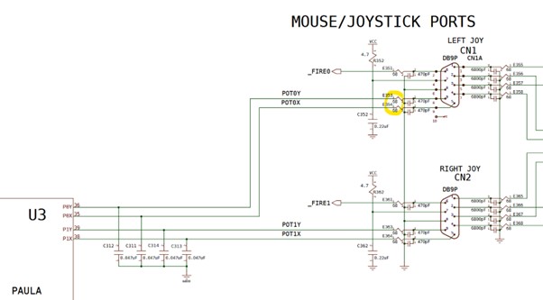
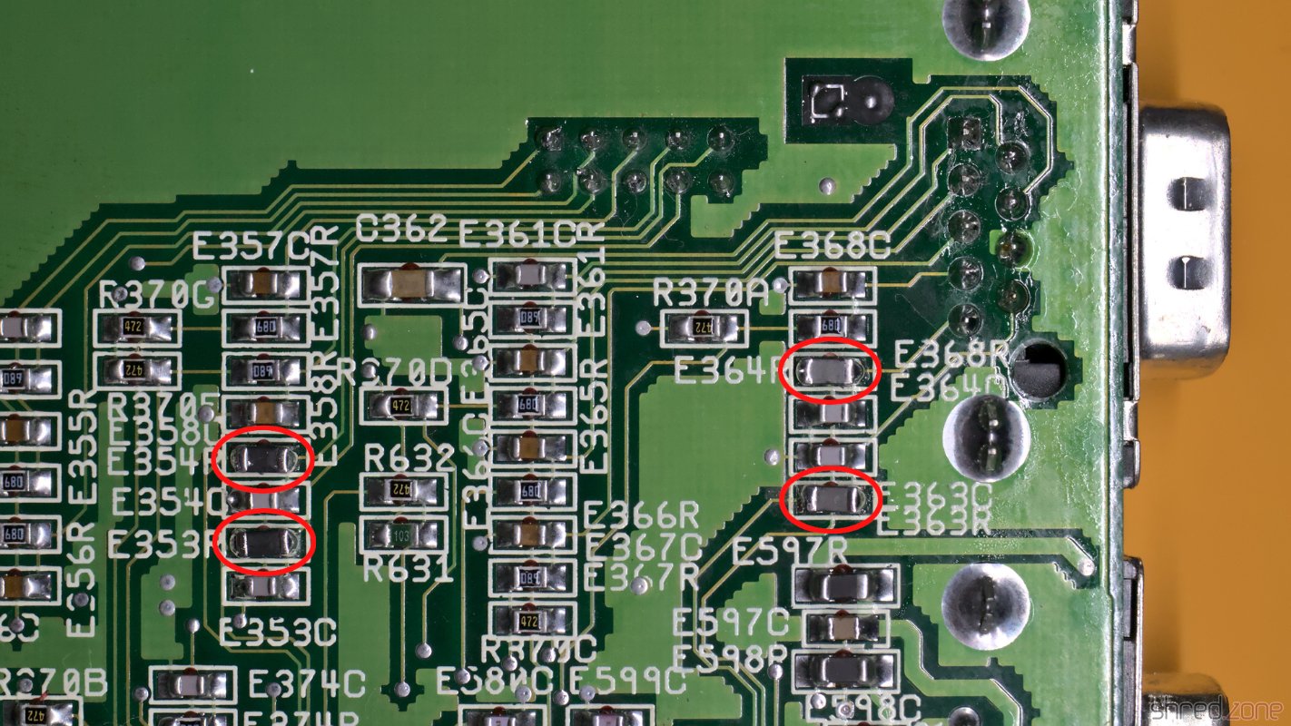
If like me you decide it's only the one DB9 port you wish to modify (the outer most one) then the resistors you're replacing are E354R and E353R which are on the left in the below picture:
My approach to swapping out these SMD resistors are as follows, but your technique may differ.
- Put some flux on the two resistors
- Set your iron to approx 230 deg C with a fine tip
- Get some fresh solder onto both ends of the two resistors
- With your tweasers ready, start to heat up both ends of the resistor, a bit of extra solder on your iron should ensure with your iron on the top of the resistor it heats up both ends and the resistors slides off
- Once removed (hopefully not with adjacent cap getting removed) cut a small piece of braid and clean off the pads
- Now add a SMALL amount of new solder to one pad for each resistor while leaving the other pad clean. I do that so when I position the new bead with my tweasors, I only need to heat one pad to melt the solder and get the new inductor flat on the board in the right position
- With your tweasers carefully extract the bead from it's packaging and move it over into position on the board. Using your tweasers the idea is to hold the bead while you carefully melt the solder on the one pad so it lies flat. Getting it positioned correctly is key and magfnification really helps here. If it's not quite lined up reposition with the tweasers after meleting the one end with the solder
- With one end soldered and the bead in the correct position you carefully put a small amount of solder on the other end without worring about the bead moving around and you're done